Gas insulation is the most common of the air at atmospheric pressure. Gases are commonly found in dielectric insulating medium, such as Nitrogen (N2), Carbon dioxide (CO2), Freon (CCI2F2) and Sulphur Hexafluoride (SF6).
By applying, low voltage and small amount of current flow, the electrodes and insulation retain its electrical properties. Then by applying, high voltage and large amount of current flow, the insulation increases sharply and an electrical breakdown occurs.

Figure 1 Current-Voltage relationship in breakdown region
Figure 1 above, is the gases of dielectric breakdown as in current and voltage non-linear relationship. As in region 1, a small amount of current can be induced ohmically. In region 2, It is then brought to a state of saturation. In region 3, by continue increase the voltage as a result in rise of current an exponential manner, although the current density is still insufficient to cause complete dielectric breakdown. In region 4, as an observed of photoionization, finally the electron avalanche evolves forming a plasma channel (at the tip), which will convert the material into a conductor. Here, the electrical discharges have two types, such as non-sustaining discharges and self-sustaining discharges. The spark breakdown is the transition of a non-sustaining discharge into a self-sustaining discharge.
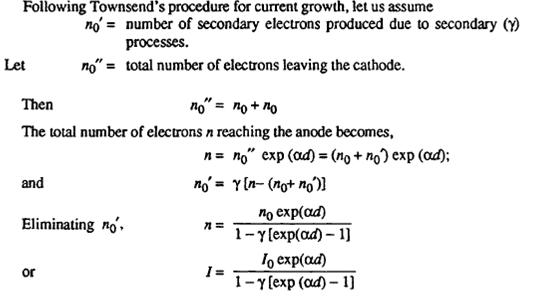
In Townsend’s current growth equation, let α be average number of ionizing collisions made by an electron per centimetre travel in the direction of the field (α depends on gas pressure p and E/p and is called the Townsend’s first ionization coefficient).

Figure 2 Ionization of the Townsend’s method
From the figure 2 above, at any distance x from the cathode, the number of electrons be nx. Electrons nx travel a further distance of dx will rise to (αnxdx) electrons.

The secondary ionization coefficient γ is define in the same way as α, whereas the net number of secondary electrons produced per incident positive ion, photon, excited particle or metastable particle and total value of γ is the sum of the individual coefficients due to three different processes. It is a function of gas pressure p and E/p.
As in Townsend’s breakdown criterion, is the total average current in the gap before occurrence of breakdown. Distance between the electrondes d is increased, the denominator of the equation tends to zero and at some critical distance d = ds.

For values of d < ds, I is approximately equal to Io and if the external source for the supply of Io is removed, I become zero. If d = ds, I à α and the current will be limited only by the resistance of the power supply and the external circuit. The Townsend’s breakdown criterion as below

Normally, exp (α d) is very large and hence reduced the above equation

For given a gap spacing and at a pressure, the value of the voltage V which gives the value of α and γ satisfying the breakdown criterion is called the spark breakdown voltage Vs and the corresponding distance ds is called the sparking distance.
Streamer theory in breakdown gases is a very fast and positive space change extends to the cathode very rapidly resulting in the formation of a streamer. Comparatively narrow lumimous tracks occurring at breakdown at high pressures. As soon as the streamer tip approaches the cathode, a cathode spot is formed and a streams of electrons rush form the cathode to neutralize the positive space charge in the streamer, which result a spark and spark breakdown has occurred. As shown in figure 3 and 4 diagrams below

Figure 3 Effect of space charge produced by an avalanche on the applied electric field

Figure 4 Cathode directed streamer
In figure 4 above, which (a) shows the stage when avalanche has crossing the gap, (b) shows that the streamer has crossed half the gap length and (c) shows that the gap has been bridged by a conducting channel.
Paschen’s law that the breakdown criterion in gases as given equation below
Where the coefficients α and γ are functions of E/p,

Substituting for E in the equation above for α and γ, as rewrite equation below

Below shows the breakdown clearances at high frequency as in figure 5

Figure 5 Formation of corona in large clearances at high frequencies. EC denotes the critical field strength (corona inception)
The breakdown voltages (Ub) of clearances (range between 0.5 mm to 4.0 mm) are frequency dependent, as in figure 6 below shows

Figure 6 Breakdown at high frequency in air at atmospheric pressure, homogeneous field, frequency range 50 Hz to 25 MHz
The vacuum can be classified as
High vacuum : 1 x 10⁻³ to 1 x 10⁻⁶ Torr
Very High vacuum : 1 x 10⁻⁶ to 1 x 10⁻⁸ Torr
Ultra High vacuum : 1 x 10⁻⁹ Torr and below
From the research paper samples as below cited,


Figure 7 Field calculation model and analysis result of vacuum interrupter and definition of configuration parameters of center shield

Figure 8 Optimization method of electrode surface
Non-uniform Air gap characteristics in positive streamer propagation and breakdown, shows in figure 9, 10, 11 and 12 below

Figure 9 Experimental setup of the positive streamer propagation

Figure 10 Definition of primary and secondary streamer current and time to Breakdown

Figure 11 Discharge waveforms and images (V = 28kV, g = 15 mm)

Figure 12 Discharge waveform and fast-framing images leading to Breakdown (V = 30kV, g = 15 mm)
Vacuum Insulator analysis of coaxial high voltage insulation at 800kV, as shown in figure 13, 14, 15 and 16 below

Figure 13 Outline of the TPG700 (1) Tesla transformer (PFL), (2) Main switch, (3) Transmission line, (4) Vacuum insulator and (5) Diode

Figure 14 Mechanical drawing of the vacuum insulator (1) Inner conductor, (2) Transformer oil, (3) Anode shield, (4) Insulator, (5) Vacuum, (6) Cathode shield and (7) Outer conductor


Figure 15 E-field magnitude and interface distribution of the vacuum insulator

Figure 16 Schematic illustration of the electric-thermal model